Wires
You need wiring to connect the individual solar panels together at a junction point, and then to connect that junction point to the charge controller. Many (me included) route the wires down the refrigerator vent so no extra holes are made in the roof. Then you need another set of wires to go from the charge controller to your battery bank, and wires to connect the individual batteries together in your bank.
What kind of wire do you need? To avoid inadvertently sabotaging your own system, get wiring that is big enough to minimize voltage drop along your wiring runs. My system uses 6AWG (6 gauge) wire from each solar panel to a junction box on the roof (about 3 feet of wire from each panel to the box), then 4AWG (4 gauge) from there down to the charge controller, and then another run of 4 AWG from the charge controller to the batteries. This is probably a bit of overkill considering the relatively low wattage of my system, but I wanted to overbuild it a bit in case I ever want to add more wattage to the roof.
Voltage Drop
Why is minimizing voltage drop so important? Well, let's say you have 400 watts on the roof, your wiring run to the controller is 45 feet long and you're using 10 gauge wire for that run (the size many RV manufacturers use in pre-wiring RVs for solar). In full sun and assuming maximum panel output, your array is producing (as an example) 17.4 volts and about 23 amps. But with such small wire, you have a roughly 11.9% voltage drop along the line, so only about 15.3 volts are reaching your controller. That might sound like plenty, but remember we are talking optimum conditions. In cases where it is cold outside your temperature sensor on the controller is going to want to bump up the voltage to compensate, even more so when equalizing, and it could very likely run short of volts to do that.
Also, if you have an MPPT controller, limiting the number of volts available to it will diminish the advantages to having MPPT at all, and after paying such a premium price to have that technology in your rig it would be a real shame to cripple it by installing wires that are too small in your system. Use a voltage drop calculator such as the one below to determine voltage drop along your proposed wire run:
Voltage Drop Calculator
Minimizing voltage drop is even more critical between your batteries and charge controller. If you've got 10 gauge wires running 10 feet from your controller to the batteries for that 400 watt system, you've got a 3.11% voltage drop at 14.8v and 23 amps, which results in a loss of 0.46v over that ten feet. So while the controller is sending the batteries 14.8 volts, the batteries are only receiving 14.34 volts, almost half a volt less than set point for my 6v batteries. That results in chronic undercharging. And in cases where the controller also uses those wires to measure the battery's state of charge, that voltage drop also results in inaccurate readings. "Garbage in, garbage out" as they say in the IT industry.
Some people connect the output wires from their charge controllers to the output connections on their converter rather than running the wires directly to the batteries. I would strongly advise against doing this, unless you know exactly how long the wire run is from the converter to the batteries, what size wire is used there and you have determined that the voltage drop is within an acceptable limit. If those wires are long and/or too small, you're going to be introducing too much voltage drop into the system.
Don't cut corners on the wiring. Don't cripple your system by doing this. Larger wire costs a little more, but it will pay off in the long run by helping to maximize the efficiency of your system.
It is true that at lower loads your voltage drop will be less pronounced. So on cloudy days you will have less voltage drop between the controller and the panels than you would have otherwise. And in absorption stage as the controller cuts the amperage output down, voltage drop will be reduced along the wire run between the controller and batteries.
But I like planning for the worst case scenario, and building a little overkill into my system. The result of doing that with my solar system has meant never running short of power. Not even once. If you want to save a little up-front cost with your system by cutting a few corners, that's your business, but keep in mind that it might bite you in the butt later. Many people whose systems have been put together with undersized wire suffer the consequences of batteries that never get fully charged, and many of them jump to the conclusion that they don't have enough panels on the roof. In reality, their wiring is choking the system, and adding more wattage on the roof without upgrading the wiring will just make the voltage drop even worse due to higher amperage coming down from the panels.
Besides the voltage drop issue, if the wire is excessively small it could potentially be a fire hazard. Higher voltage drop means higher resistance in the wire, and with resistance comes heat. The greater the resistance, the more heat produced. Even if a fire isn't produced, you could easily melt fuse holders or the insulation around the wire, creating a shorting hazard.
Would you rather fill a swimming pool with a half-inch garden hose, or a 3-inch fire hose? I'll take the fire hose, every time.
Saving Money on Wire

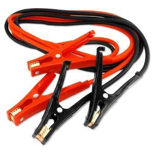
20-foot, 4 gauge copper jumper cables
Even if your wire run from the panels to the controller is too long for this to work for you there, it should work between the controller and batteries, because you don't ever want a wire run even 20 feet long there. In fact, if you can keep it to six feet that would be great. Or three. The shorter, the better. Play with the Voltage Drop Calculator to see why. You could use any excess left over from the jumper cables on the wire run from the controller to the kill switch (along the wire run from the panels).
Wiring Panels in Series to Reduce Voltage Drop
As I mentioned in an earlier post, you can get away with using smaller wires between the panels and controller if your system has higher voltages (for example, wiring two 17.4v panels in series to produce 34.8v), because voltage drop is not as bad in higher voltage DC systems. You must have a controller that has the capability of bringing that voltage back down for your 12v battery bank, however. To show how this works, here's an example:
Let's say we have 220 watts on the roof that consists of two 110 watt panels of 17.4v and 6.28 amps each, and 30 feet of ten gauge wire connecting them to the charge controller. Connected in parallel, together they are sending 17.4 volts and 12.56 amps down that wire. Over the 30-foot run, there is a 4.31% voltage drop according to the voltage drop calculator. We've already lost almost ten watts into thin air.
Now let's use the exact same system and the only thing we're changing is wiring the panels in series instead of parallel. That doubles the voltage but not the amps, so now we're sending 34.8 volts and 6.28 amps down the wire to the charge controller (note that this is still 220 watts). According to the voltage drop calculator, we now have a voltage drop of only 1.09%. So now we've only lost a little over 3 watts, and all we did was change the way the wiring was connected!
Of course this assumes our charge controller is capable of handling this higher voltage from the panels. Make sure you buy a controller that has this capability if you are interested in this type of setup. But keep in mind, if your system would otherwise work fine with a PWM controller it could be cheaper to just use bigger wire and keep panels wired in parallel rather than buying an expensive MPPT controller with this capability. Do some research, and do the math for your own system.
Important note: This doesn't change anything between the controller and the batteries - you still need adequately heavy wire there because those wires will still be in the 12v to 14+ volt range.
Fuses
Although it may not strictly be required, depending on your panel configuration, I think it is a good idea to add a fuse or circuit breaker to the positive side of each solar panel, assuming they're wired in parallel. In the case of series wired panels, add a fuse on each series circuit. A fuse should also be added along the positive lead from the charge controller to the batteries, near the battery bank. To decide what size fuses or circuit breakers to use, this document might be helpful.

20 Amp Circuit Breaker

Inline Fuse Holder
Switches
You also need to provide a kill switch along the wire run from the junction box on the roof to the controller, as well as between the controller and the battery bank. Wire these in along the positive cable on each of those runs. This will provide you a way to shut the system down easily when you need to perform maintenance.

Kill Switch
In addition to wires, fuses and switches, you'll need connectors for your wires and mounting hardware for your panels. For my system I just picked up some angle iron at the hardware store to build a rack for the panels, and got all the wire lugs and various connectors, nuts and bolts there as well. I built the rack in such a way that the panels were mounted about six inches from the end of the rack that pivots when they are tilted up. This way, when tilted, the panels are raised up above any possible shade from my vent covers.
The rack is mounted to the luggage rack already on top of my camper, which I never used anyway. This worked out well. If you need to mount panels directly on the roof, there are various ways of doing that, such as bolts with sealant through the roof, or super sticky double-sided 3M tape, which I have zero experience with but have heard about. And since heat affects solar performance you might want to make sure there is an air gap between your panels and the roof for cooling purposes.
Personally, I hate putting holes in RV roofs. It's just another leak waiting to happen. But the thought of tape holding my expensive panels to the roof and the associated risk of injury or death, not to mention potential damage and liability if they were to blow off, is more than a little scary as well. If I didn't already have a roof rack to attach them to, I think I would consider mounting a panel rack by attaching cross bars across the width of the roof that bolted to the sides of the rig instead of the roof itself. At least then water would never pool over the holes.
Then again, my roof leak paranoia is probably showing. Maybe with the proper sealant roof holes would be fine.
Let's Move On
OK, so now you've got all the components figured out as well as the necessary hardware to wire it all together. What else do you need to worry about? Well, there are several things. First, where to mount your panels. Second, where to mount your controller. Third, how to monitor the system? This is all covered in Part 9, Installation and Monitoring.
Hey just wanted to give you a quick heads up and let you know a
ReplyDeletefew of the pictures aren't loading correctly.
I'm not sure why but I think its a linking issue.
I've tried it in two different web browsers and both show the same results.
Thanks for the heads up. The pics were hosted on a free photo hosting site that decided to make that option available only to paid subscribers. Unfortunately they failed to notify me that this was going to happen and instead just barred access. I've re-linked all the photos now.
Delete